This is the multi-page printable view of this section.
Click here to print.
Return to the regular view of this page.
Concepts
How to dismantle an IBM mainframe … and not die trying
An IBM mainframe server is designed as a highly coupled monolithic architecture. Application programs communicate with each other and with data repositories by exchanging memory addresses (pointers).
How is it possible to break down this monolith in a step-by-step and secure way so that the risks of the process are minimised?
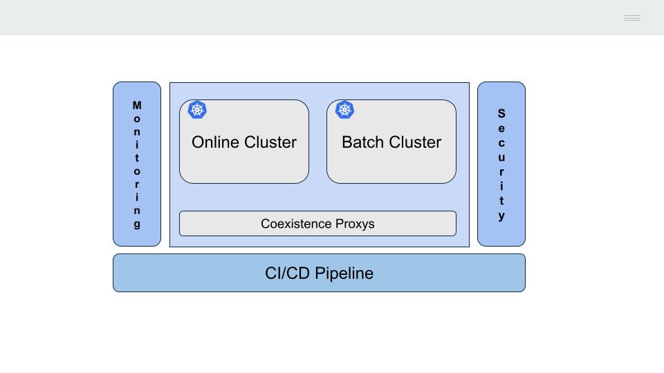
1 - Strangler Fig Pattern
How do you safely break down a monolithic architecture?
The IBM mainframe server is a monolithic system, there is no clear separation between the different levels or layers of the technical architecture, all processes reside on the same machine (CICS, batch, database, etc).
Shared memory is used for communication between the different processes (calls between programs, access to the DB2 database, etc.).
This mechanism has the advantage of being very efficient (necessary in the last century when the cost of computing was very high), but the disadvantage of tightly coupling the processes, making it very difficult to update or replace them.
This last characteristic makes the most viable alternative for the progressive migration of the functionality deployed on the mainframe to adopt the model described by Matin Fowler as Strangler Fig.
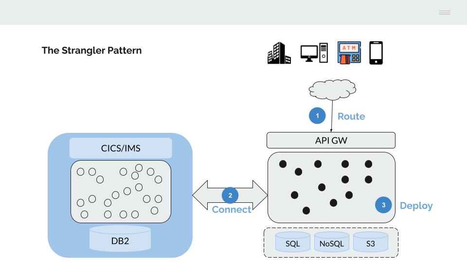
- Traffic from the channels is gradually moved to an API gateway, which is used to route it to the back-end platforms (mainframe or next-generation)
- The two platforms are connected to enable a phased deployment of applications
- Gradually migrate the applications until the IBM mainframe server is emptied of its content
API Gateway
The connection from the channels is progressively routed to an API gateway.
This API gateway has two main functions:
-
On the one hand, we can think of this API Gateway as replacing the functionality provided by the CICS Transactional Monitor, which manages the following:
- The communication (send/receive) with the channels, we will replace the 4-character transaction codes of CICS with well-formed APIs
- The authentication process, replacing CESN/CESF and RACF with a mechanism based on LDAP
- Authorising operations, replacing RACF with a mechanism based on ACLs/RBAC.
-
On the other hand, this API gateway is used to route traffic from the channels to the target platform, gradually replacing IBM mainframe server functionality with equivalent next-generation platform functionality.
In order to enable the progressive deployment of functionality, it is necessary to connect the two platforms. These connection mechanisms are essential to avoid “big bang” deployments, to facilitate rollback in the event of problems, to enable parallel deployments, etc, in short, to minimise the risks inherent in a change process such as this.
There are two basic connection mechanisms
DB2 Proxy
z/DB2 provides several mechanisms for accessing DB2 tables using jdbc and odbc drivers.
This is similar to the functionality provided by CICS when connecting to DB2. The DB2 proxy manages a pool of database connections, the identification/authorisation process and the encryption of traffic.
CICS/IMS Proxy
Allows transactions to be executed over a low-level connection based on TCP/IP sockets.
Deployment of functionality
When migrating mainframe functionality to a cloud architecture, there are three alternatives.
Rebuild
The functionality can be redesigned, written in a modern programming language (java, python, go, …) and deployed as a microservice on the next-gen platform.
These new programs can reuse the mainframe platform through the coexistence architecture described above.
- Execute SQL statements accessing DB2 through the DB2 proxy.
- Call the CICS/IM Proxy to invoke a mainframe transaction.
Refactor
In this case, we are compiling the COBOL mainframe code on the next-generation platform (Linux-x86/arm) and deploying it as a microservice. This is equivalent to any other microservice built in Java, Python, go, etc.
Replace
Invocation of APIs provided by a third-party product that implements the required functionality.
The above alternatives are not exclusive, different alternatives can be chosen for each functionality or mainframe application, but they all share the same technical architecture, the same pipeline for building and deploying and benefit from the advantages offered by the new technical platform (security, encryption, automation, etc.).
2 - Microservice model
What microservices model do we need for COBOL?
The model for building microservices must allow:
- The use of different programming languages (including COBOL)
- Be interoperable (with each other and with mainframe logic)
- Migrate data between platforms (mainframe DB2 / next-gen SQL).
To do so, the Hexagonal Architecture will be used as a reference model.
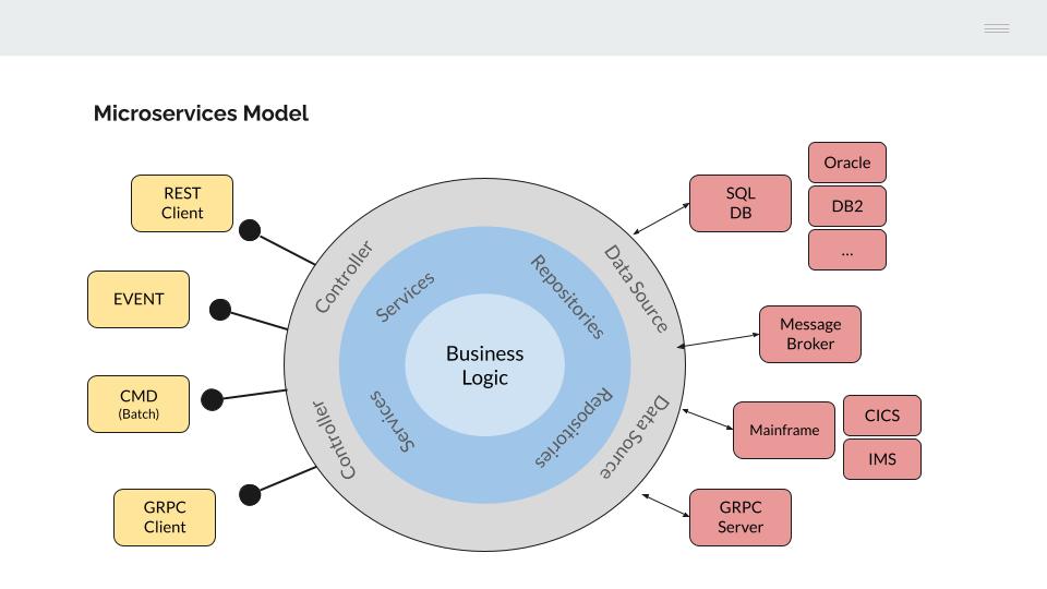
Looking at the left-hand side of the model, the application programs are decoupled from the interface used to execute them. This concept should be familiar as it is the model used to build COBOL applications on an IBM mainframe.
The COBOL language originated in the 1960s when all processing was done in batch. IBM later developed its CICS/IMS transactional monitors to allow COBOL programs to connect to devices in its SNA communications architecture.
COBOL programs only handle data structures (COBOL COPYBOOKS) and it is the transactional monitor that manages the communication interface (LU0, LU2, Sockets, MQSeries, etc.).
Similarly, the business functionality implemented in microservices is independent of the interface used to invoke it through a specific controller.
This allows us to reuse application logic from different interfaces:
- REST API (json)
- gRPC API (proto)
- Events (Kafka consumers)
- Console (batch processes)
- Etc.
COBOL programs are perfectly adapted to this model, only a conversion process from the chosen interface (json / proto) to a COPYBOOK structure is required.
On the right-hand side of the model, the business logic should be agnostic to the infrastructure required for data retrieval.
Although this model has obvious advantages, the level of abstraction and complexity to be introduced in the design and construction of the microservices is high, which leads us to make a partial implementation of the model, focusing on two relevant aspects that provide value;
SQL databases
The mainframe DB2 is accessed through a proxy.
This proxy exposes a gRPC interface to allow calls from microservices written in different programming languages.
The same mechanism is replicated for access to other SQL database managers (e.g. Oracle or PostgreSQL).
Cross-platform data migration (e.g. from DB2 to Oracle) is facilitated by configuring the target data source in the microservice.
Calling CICS/IMS transactions
In this case, CICS/IMS programs are exposed as microservices (http/REST or gRPC), facilitating their subsequent migration as long as the data structure handled by the program does not change.
3 - Online Architecture
How do you migrate CICS/IMS transactions to microservices?
The answer should be quite simple, by compiling the COBOL program and deploying the object in a container (e.g. Docker).
However, there are two types of statements in the online programs that are not part of the COBOL language and must be pre-processed:
- The statements of the transactional monitor used (CICS/IMS).
- The access statements to the DB2 database
CICS statatements
Online programs are deployed on a transactional monitor (CICS/IMS) which performs a number of functions that cannot be performed directly using the COBOL programming language.
The main function would be the sending and receiving of messages.
The COBOL language has its origins in the mid-20th century when all processing was done in batch, there were no devices to connect to.
Communication is therefore managed by the transactional monitor. COBOL programs define a fixed data structure (COPYBOOK) and include CICS block statements (EXEC CICS SEND/RECEIVE) as part of their code to send or receive application messages.
The transaction monitor uses the address (pointer) and length of the COPYBOOK to read/write the message to/from it.
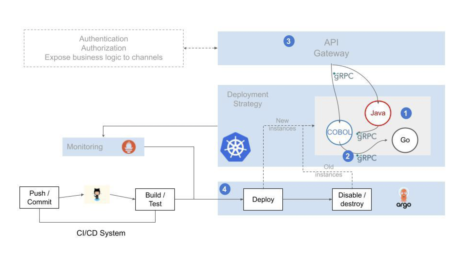
The proposed microservices model behaves like CICS/IMS, extending the gRPC/proto capabilities to the COBOL language.
-
COBOL program COPYBOOKs (data in LINKAGE SECTION) used to send/receive messages are converted to proto messages.
-
The gRPC interface (gRPC server) is managed by a special controller
-
The message is converted from proto to COPYBOOK format. The message data (string, int, float, etc.) is transformed to COBOL data (CHAR, DECIMAL, PACKED DECIMAL, etc.)
-
Finally, Go cgo is used to load the COBOL program and execute it by passing the generated data structure to it.
-
The solution allows services to be coded in modern languages that are attractive to developers. At the same time, it allows the use of programs coded in “legacy” languages, whose recoding would result in an unnecessary waste of resources.
-
Internal communication between the different services is implemented using a lightweight and efficient protocol.
-
Services are called from front-ends or third party systems through a secure, resilient and easily scalable exposing mechanism.
-
The operation is supported by automated deployment pipelines and advanced observability capabilities that provide an integrated and consistent view of the entire application flow and the health of the elements involved.
The remaining CICS statements common to application programs (ASKTIME/FORMATTIME, LINK, READQ TS, WRITEQ TS, RETURN, etc.) can be replaced directly by COBOL code (ASKTIME, RETURN, LINK) or by calling utilities developed in Go cgo.
DB2 statements
DB2 database access statements are of static type.
They must be precompiled. There are two ways to do this:
4 - Batch architecture
How do you run batch processes in an open architecture?
The following is a description of the main components of the IBM Batch architecture; it is important to understand the capabilities of each in order to replicate them on an open container-based architecture.
- JCL
- JES
- Application programs (COBOL, PL/I, etc.)
- Data (files and databases).
JCL
We can think of a JCL as a distant ancestor of a DAG (Directed Acrylic Graph), it is a set of sentences, inherited from punch card technology, that define the process and the sequence of steps to be executed.
In the JCL we find the basic characteristics of the process or job (name, type, priority, resources allocated, etc.), the sequence of programmes to be executed, the sources of input information and what to do with the output data of the process.
The main statements found in a JCL are the following
- A JOB card, where the name of the process and its characteristics are defined.
- One or more EXEC cards with each program to be executed.
- One or more DD cards defining the files (data sets) used by the previous programs.
//JOB1    JOB (123),CLASS=C,MSGCLASS=S,MSGLEVEL=(1,1),NOTIFY=&SYSUID
//*
//STEP01   EXEC PGM=PROGRAM1
//INPUT1   DD   DSN=DEV.APPL1.SAMPLE,DISP=SHR
//OUTPUT1  DD   DSN=DEV.APPL1.CUOTA,
//              DISP=(NEW,CATLG,DELETE),VOLUME=SER=SHARED,
//              SPACE=(CYL,(1,1),RLSE),UNIT=SYSDA,
//              DCB=(RECFM=FB,LRECL=80,BLKSIZE=800)
//*
JES
The JES is the z/OS component (subsystem) responsible for batch processing. It performs two main tasks:
- Scheduling the batch processes
- Assigning the process to a class or initiator (jobs can be assigned to specific queues)
- Defining the priority of the process
- Allocating/limiting the resources assigned to the process (memory, time, etc.)
- Control the execution sequence (STEPs) of the process
- Execute programs
- Validate the JCL statements
- Loading programs (COBOL, PL/I) into memory for subsequent execution
- Assigning the input/output files to the symbolic names defined in the COBOL PL/I application programs
- Logging
Application programs
Programs, usually coded in COBOL, that implement the functionality of the process.
The executable program resulting from the compilation of the source code is stored as a member of a partitioned library (PDS).
A specific card in the JCL (JOBLIB / STEPLIB) identifies the libraries from which the programs are to be loaded.
The JES calls the main program of the process (defined in the EXEC card of the JCL), which in turn can call various subroutines statically or dynamically.
Data
Data is accessed mainly through the use of files (datasets) and relational databases (DB2).
The input and output files are defined in the programs by means of a symbolic name.
         SELECT LOAN ASSIGN TO "INPUT1"
         ORGANIZATION IS LINE SEQUENTIAL
         ACCESS IS SEQUENTIAL.
The assignment of symbolic names to read/write files is done in the JCL, via the DD card.
//*
//INPUT1   DD   DSN=DEV.APPL1.SAMPLE,DISP=SHR
The files are generally of one of the following types
- Sequential, the records must be accessed sequentially, i.e. to read the 1000th record, the previous 999 records must be read first.
- VSAM. There are different types of VSAM files, and it is possible to access the records directly using a key (KSDS) or a record number (RRDS).
In the case of access to a database (DB2), the information necessary for the connection (security, database name, etc.) is passed as parameters in the JCL.
Mainframe Batch Migration to Open Architecture
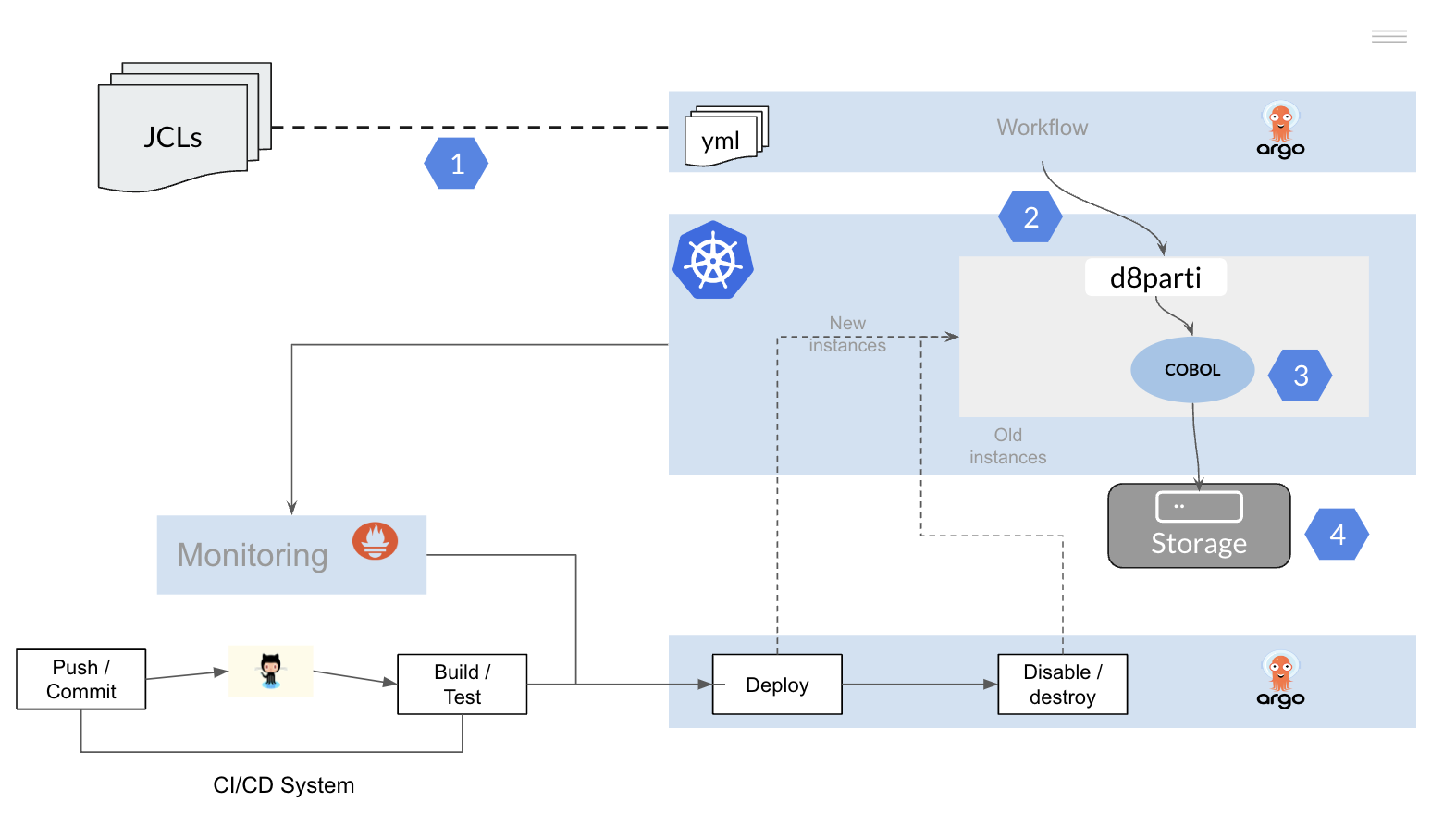
To migrate batch processes built on mainframe technology, we will replicate the functionality described above on a Kubernetes cluster.
It is therefore necessary to:
- Convert the JCLs (JOBs) to a tool or framework that allows the execution of workflows on a Kubernetes platform.
- Replicate the functionality of the JES to allow the scheduling and execution of COBOL PL/I programs on the Kubernetes cluster.
- Recompile the application programs.
- Provide access to data (files and databases).
4.1 - Converting JCLs
How to convert a JCL mainframe into a DAG?
Below is a simple example of how to convert a JCL into an Argo workflow (yaml).
Other frameworks or tools that allow the definition of DAGs and have native integration with the Kubernetes platform can be used.
apiVersion: argoproj.io/v1alpha1
kind: Workflow
metadata:
 name: batch-job-example
spec:
 entrypoint: job
 templates:
   - name: job
     dag:
       tasks:
         - name: extracting-data-from-table-a
           template: extractor
           arguments:
         - name: extracting-data-from-table-b
           template: extractor
           arguments:
         - name: extracting-data-from-table-c
           template: extractor
           arguments:
         - name: program-transforming-table-c
           dependencies: [extracting-data-from-table-c]
           template: exec
           arguments:
         - name: program-aggregating-data
           dependencies:
             [
               extracting-data-from-table-a,
               extracting-data-from-table-b,
               program-transforming-table-c,
             ]
           template: exec
           arguments:
         - name: loading-data-into-table1
           dependencies: [program-aggregating-data]
           template: loader
           arguments:
         - name: loading-data-into-table2
           dependencies: [program-aggregating-data]
           template: loader
           arguments:
   - name: extractor
   - name: exec
   - name: loader
Batch ETL process divided into three phases:
- The extraction of information from a set of DB2 tables (template extractor).
- Transforming and aggregating these tables using COBOL applications (template exec).
- Loading the resulting information (template loader)
Each JOB is transformed into a DAG in which the sequence of tasks (STEPs) to be executed and their dependencies are defined.
Similarly to PROCS in the mainframe, it is possible to define templates with the main types of batch tasks of the installation (DB2 data download, execution of COBOL programs, file transfer, data conversion, etc.).
Each STEP within the DAG is executed in an independent container on a Kubernetes cluster.
Dependencies are defined at the task level in the DAG and non-linear execution trees can be built.
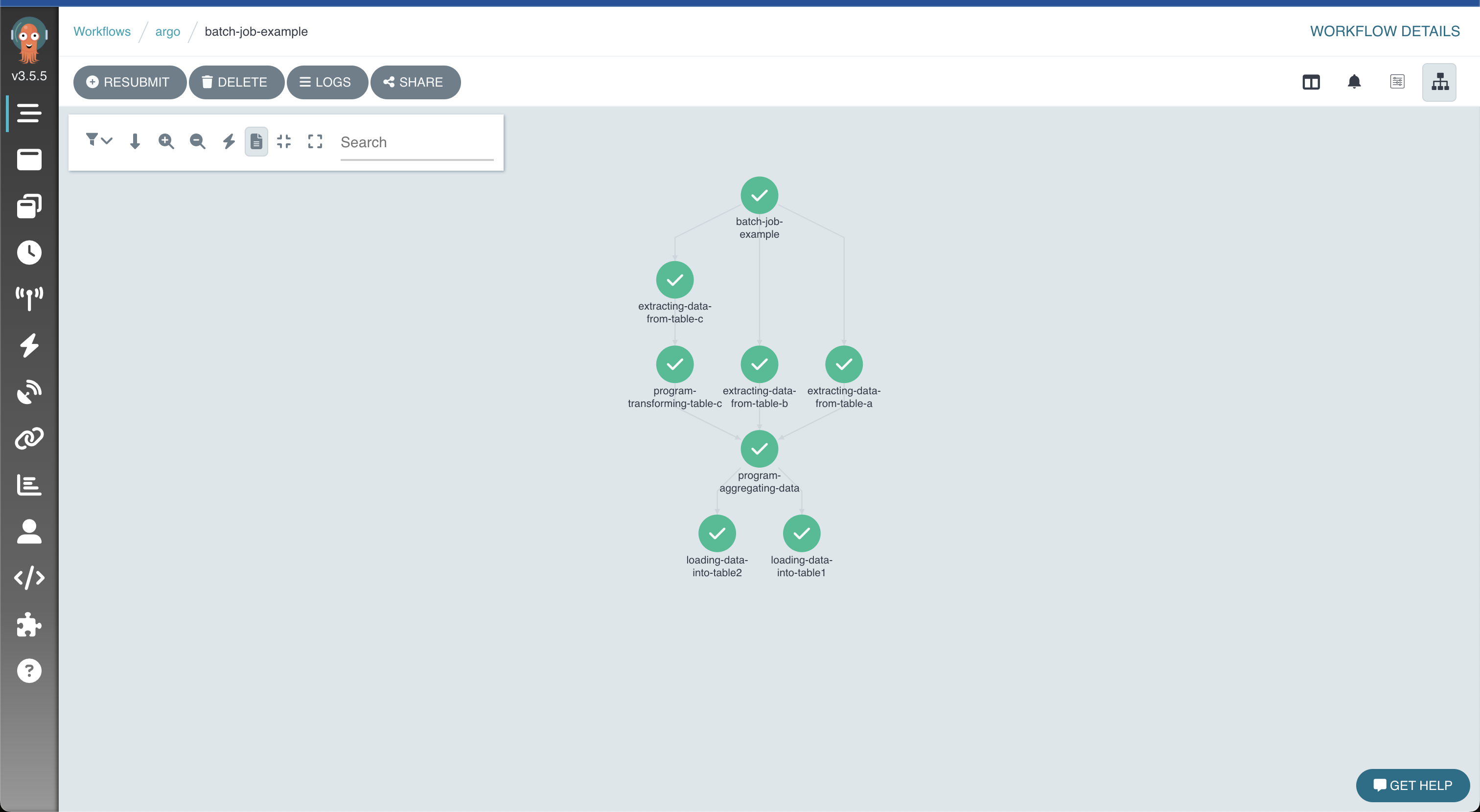
Result of the execution of the process, graphically displayed in Argo
4.2 - Replicate JES functionality
How to replicate how the JES works?
If you’re familiar with The Twelve-Factor App, you’ll know that one of its principles is to make the application code independent of any element that might vary when it’s deployed in different environments (test, quality, production, etc.).
Storing the configuration in the environment
An app’s config is everything that is likely to vary between deploys (staging, production, developer environments, etc)
The Twelve-Factor App. III Config
We can translate the information contained in the JCLs into configuration files (config.yml), which contain the necessary information for running the code in each of the environments defined in the installation (resource allocation, connection to the database, name and location of the input and output files, level of detail of the logging, etc.).
To understand what functionality we need to replicate, let’s divide a JCL into two parts:
- JOB card
- EXEC and DD cards
//JOB1    JOB (123),CLASS=C,MSGCLASS=S,MSGLEVEL=(1,1),NOTIFY=&SYSUID
//*
//STEP01   EXEC PGM=BCUOTA
//INPUT1   DD   DSN=DEV.APPL1.SAMPLE,DISP=SHR
//OUTPUT1  DD   DSN=DEV.APPL1.CUOTA,
//              DISP=(NEW,CATLG,DELETE),VOLUME=SER=SHARED,
//              SPACE=(CYL,(1,1),RLSE),UNIT=SYSDA,
//              DCB=(RECFM=FB,LRECL=80,BLKSIZE=800)
//*
JOB card
In the JOB card, we will find the basic information for scheduling the process in Kubernetes:
- Information needed to classify the JOB (CLASS). Allows you to classify the types of JOBs according to their characteristics and assign different execution parameters to them.
- Define default output (MSGCLASS).
- The level of information to be sent to the std out (MSGLEVEL)
- Maximum amount of memory allocated to the JOB (REGION)
- Maximum estimated time for execution of the process (TIME)
- User information (USER)
- Etc.
In Kubernetes, the kube-scheduler component is responsible for performing these tasks. It searches for a node with the right characteristics to run the newly created pods.
There are several options;
- Batch processes can use the Kubernetes job controller, it will run a pod for each task (STEP) of the workflow and stop it when the task is completed.
- If more advanced functionality is required, such as defining and prioritising different execution queues, specialised schedulers such as Volcano can be used.
- Finally, it is possible to develop a Kubernetes controller tailored to the specific needs of an installation.
EXEC & DD cards
In each STEP of the JCL we find an EXEC tab and several DD tabs.
It is in these cards that the (COBOL) program to be executed and the associated input and output files are defined.
Below is an example of how to transform a STEP of JCL.
---
stepname: "step01"
exec:
 pgm: "bcuota"
dd:
 - name: "input1"
   dsn: "dev/appl1/sample.txt"
   disp: "shr"
   normaldisp: "catlg"
   abnormaldisp: "catlg"
 - name: "output1"
   dsn: "dev/appl1/cuota.txt"
   disp: "new"
   normaldisp: "catlg"
   abnormaldisp: "delete"
For program execution, EXEC and DD instructions are converted to YAML. This information is passed to the d8parti controller, which specialises in running batch programs.
The d8parti controller acts like the JES:
- It is in charge of the syntax validation of the YAML file
- It maps the symbolic names in COBOL programs to physical input/output files
- Loads COBOL into memory for execution
- Writes monitoring/logging information
4.3 - Program compilation
How to reuse mainframe application programs?
The mainframe COBOL PL/I programs are directly reusable on the targeted technical platform (Linux).
As mentioned above, the d8parti module will be responsible for the following tasks
- Initialise the language runtime (i.e. COBOL)
- Assign the input/output files to the symbolic names of the program
- Loading and execution of the main program (defined in the EXEC tab of the JCL)
This main program can make various calls to other subroutines using a CALL statement. These calls are managed by the runtime of the language used.
We can visualise this operation as an inverted tree
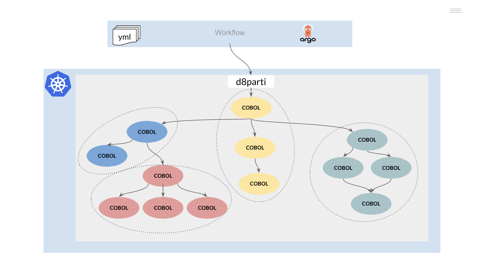
Compiled programs can be stored in a shared directory and loaded at runtime (dynamic CALL), mimicking the IBM mainframe (STEPLIB).
However, it is possible to change the above behaviour and implement an immutable container model, which has several advantages over the above model. In this case, the previous execution tree should be functionally decomposed into one or more repos.
Modifying any of the components of these repos generates a new version of the same and the corresponding regeneration of the container(s) that use it.
With this strategy we achieve
- Simplify the application development and testing process.
- Enable incremental introduction of changes to the system, minimizing risks
- Enable the portability of processes to different Cloud platforms (on-prem, on-cloud).
Once a business function has been isolated in a container with a standard interface, it can be modified or rewritten in any other programming language and deployed transparently without affecting the rest of the system.
4.4 - Data access
How to access data stored in SQL files and databases?
Files
In mainframe architecture, a Data Set is a set of related records stored in a UNIT / VOLUME.
To understand these concepts, we need to go back to the days when mass storage devices were based on tapes or cartridges. So when a process needed to access the information in a data set, the tape or cartridge had to be mounted in a UNIT and identified by a name or VOLUME.
Today, information resides on disk and does not need to be mounted/unmounted for access, we can compare mainframe VOLUMEs to an NFS share.
Different mount points can be defined for the application container to isolate the information and protect access (e.g. by environment, development and production). The containers are accessed via SDS (Software Define Storage) to decouple the storage from the process.
Finally, the mainframe files need to be transferred and converted (EBCDIC) into Linux files for use on the target platform. This process can be automated using off-the-shelf tools or using Spark data conversion processes.
SQL databases
The main mainframe database engine is IBM DB2, although other types of products (IMS DB, IDMS, Adabas) are still in use.
For DB2 applications, there are two main strategies for accessing data:
- Replication of DB2 data on a new SQL database (e.g. PostgreSQL).
- Accessing DB2 on the mainframe platform from the Kubernetes cluster using the Coexistence Proxy (DB2 Proxy).
In the first case, replication tools (e.g. IBM CDC) or ETL processes (e.g. using Spark) are used to replicate the data from the DB2 tables to a new SQL database.
The DB2 SQL statements (EXEC SQL … END-EXEC.) are pre-compiled to be able to access the new database manager, it is necessary to make small changes in the SQL to adapt it, but there is a methodology and tools to carry out this process automatically:
- DDL replication (tablespaces, tables, indexes, columns, etc.)
- Adapting the DATE/TIME data types.
- SQLCODEs
- Upload and download utilities
- Etc
The main drawback of this strategy is the need to maintain the data integrity of the model, generally the referential integrity model of the database is not defined in the DB2 manager, it must be deduced by the logic of the applications.
All read/update processes that access the affected tables (whether batch or online) must either be migrated to the new platform or a coexistence/replication mechanism must be defined between the platforms (mainframe DB2 / next-gen SQL). This mechanism must maintain data integrity on both platforms until the migration process is complete.
For tables containing master data accessed by a large number of applications, this coexistence is particularly critical.
There is no need to maintain data integrity between platforms (mainframe / next-gen) if you choose to continue accessing DB2 mainframe through the coexistence proxy.
Processes (online or batch) can be migrated one at a time and in stages (canary deployment).
Once the process of migrating the application programs (Online and Batch) has been completed, the data can be migrated to a new database on the target platform (Next-gen).


